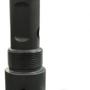
C-1 Running Tool
Purpose
To run Baker style “S”, “W”, and “Z”, lock assemblies.
Operation
The “C-1” pinning procedures is done in one of two ways. Pinning the lock assemblies only, the two upper outer series of pin holes are used, pinning under the fishing neck of the lock assembly, brass shear stock is used.
Pinning the “C-1” running tool to the “S” selective lock assemblies will require an “A” shank to retract down facing locks, to avoid the lock assembly hanging up while lowering assembly into the well. The up facing locks trail enabling them to locate in the nipple profile during upward jarring of the setting sequence.
Pinning to plugs with removable equalizing mandrels, the lock assembly is pinned in the same manner under the fishing neck, except using the lower outer series of pin holes with brass shear stock. The equalizing mandrel is pinned through an upper center pin hole, or one of the upper outer holes, this pin will be brass depending on the size of the plug being ran.The “W” and “Z” lock assemblies are pinned in the same manner, being no-go lock assemblies no shanks are required during the normal setting procedures.
To set the lock assembly in the nipple profile lower to the nipple, moderate downward jarring ensures that the lock assembly has landed to the proper depth before upward jarring is administered to set the lock assembly and shearthe “C-1” running tool pins.
Precautions
Before running check the locator ring size to make sure that it matches thenipple profile when setting selective locking assemblies.
Download Technical Datasheet


