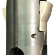
W Lock
Purpose
To offer a positive locating sequence for sub surface controls in selective “F” nipple profiles.
Description
The “W” lock assemblies have a larger OD dimension near the top of the lock mandrel which no-go’s on top of the nipple profile sealing bore preventing downward movement when locked in the nipple profile. The two locks are fitted and pinned in the body of the lock mandrel facing up to prevent upward movement of the lock assembly when locked into the nipple profile.
The “W” lock assemblies are ran in the “F” profile seating nipples having a seal bore dimension smaller than the lock assembly no-go OD dimension. Ran with a “C-1” running tool.Pulled with a “JUC” or “JDC” pulling tool and the model “B” probe to disengage the locks.
Operation
The “W” lock assembly with subsurface control is appropriately pinned to the“C-1” running tool, no shanks or locator rings are required for “C-1” running tool.
The “C-1” running tool with the “W” lock assembly and the subsurface control is attached to the tool string and lowered to the nipple profile, taking the tool string weighs above nipple depth.
Downward jarring sets the “W” lock assembly in the seating nipple profile. Upward strain ensures the lock assembly is set in the seating nipple profile,upward jarring now shears the pins in the “C-1” running tool. The “W” lock assembly is ran with the up facing locks trailing.
Precautions
Be sure the “W” lock assembly no-go OD is larger than the seal bore size ofthe desired seating nipple it is to be set in. This prevents the loss of the lockassembly and accessory out of the tubing string into the casing, should therebe no more nipples with a small enough ID for the “W” lock no-go to locate in.
Download Technical Datasheet


